In this article, we will understand the working of servo regulators. As mentioned on our product page, there are mainly three types of automatic voltage stabilizers. They are relay type, static, and servo motor controlled regulators. To understand the working of a servo voltage regulator, we need to understand its different components and their functions.
What are the components of a servo voltage regulator?
Servo motor controlled Automatic voltage regulator consists of the following components (Please refer to servo stabilizer circuit diagram shown below):
1. Buck/Boost Transformer.
Buck and Boost transformer connected between mains input and output of servo regulator. One terminal of its primary is permanently bonded to the fixed tapping of the autotransformer while another end connects to the motor shaft. Thus, the movement of the motor shaft changes the number of windings on the autotransformer. As a result, it changes the primary voltage of the buck-boost transformer.
2. Autotransformer or dimmer.
It has a toroidal shape, and it is connected between the neutral point and phase of the input power supply. It facilitates the input voltage to the primary winding of the Buck-boost transformer. It is a round shape transformer. Its basic job is to supply increase or decrease voltage to the buck-boost transformer. Depending on the rating of the servo voltage regulator, it is designed for a specific turn ratio.
3. Servo motor.
One end of Primary of Buck-Boost transformer connected to the shaft of this motor with arm and brush mechanism. When the motor moves, this arm shaft moves across the winding of the autotransformer to increase or decrease the number of winding. Hence, it adds or subtracts the primary voltage of the buck-boost transformer to correct out voltage. This motor is generally an AC Synchronous motor or DC servo motor connected, and it is fitted on top of autotransformers center point. Thus, this motor plays a very crucial role in a servo regulator.
4. Carbon brush.
The arm and brush mechanism is the heart of servo motor voltage regulators. The carbon brush attached to the arm moves on the copper winding of dimmer. Hence, it often gets erase due to its repeated use. Good quality carbon brush is suggested for the servo stabilizer to avoid replacement at the early stage.
5. Motor drive & Control Circuitry Power supply.
It is purely electronic circuitry that controls the movement of the motor. It consists of PCBs consisting of solid-state circuitry consisting of a capacitor, register, transistor Amplifier, Microprocessor, and ICs. In short, the motor drive is the mind of the servo voltage regulator. Motor drivers continuously take input about input and output voltages and accordingly send an instruction to the servo motor to adjust the number of windings.
Control Circuitry PCB boards need a constant DC power supply. Control circuitry Power supply makes available power for PCB boards. It consists of Rectifier (to convert AC to DC) and a step-down transformer.
How does a servo regulator work?
To understand the working of a servo voltage regulator, please note that voltage across secondary of Buck-Boost transformer is nothing but output voltage of stabilizer. It works as follow:
- Voltage received from the mains at the servo regulator input is continuously sensed by accessories circuitry and gives feedback to the Main control circuitry, which consists of a Microprocessor. This Microprocessor constantly receives values of input voltages. Whenever there is a high or low voltage at the input of AVR, the Microprocessor gives a trigger to the motor driver.
- Based on the amount of high voltage or low voltage observed at the input, the “motor driver” moves the servo motor across the winding of the autotransformer to increase the decrease of the number of winding. Hence, the voltage across the primary of the buck-boost transformer increase or decreases since autotransformers output is connected to the primary of buck-boost transfer. Thus, the induced secondary of the buck-boost transformer changes when there in a change in its primary voltages. The motor moves so that proper voltage should be observed across the primary of Buck-Boost transformer so that voltage across secondary should be equal to the set or desired output voltage of servo stabilizer.
- This process takes place continuously to correct input voltages and deliver stable voltage at the output of the servo motor voltage regulator.
- In the case of a 3 Phase servo regulator, each phase has its buck-boost transformer and dimmer to correct each phase independently. This type of servo voltage regulator is called an independent phase-controlled unit. It means it is as good as three Single-phase servo stabilizers in one unit.
How to buy a servo regulator?
Before buying a servo voltage regulator, you should research to select the right type, capacity, and price. Every step is essential to get the most suitable model. If you follow the following steps, then there are fewer chances of making mistakes. These steps will explain the load calculation to select the right type and supplier for your servo regulator.
Total Time: 30 minutes
Step 1: Segregate single and three-phase load.
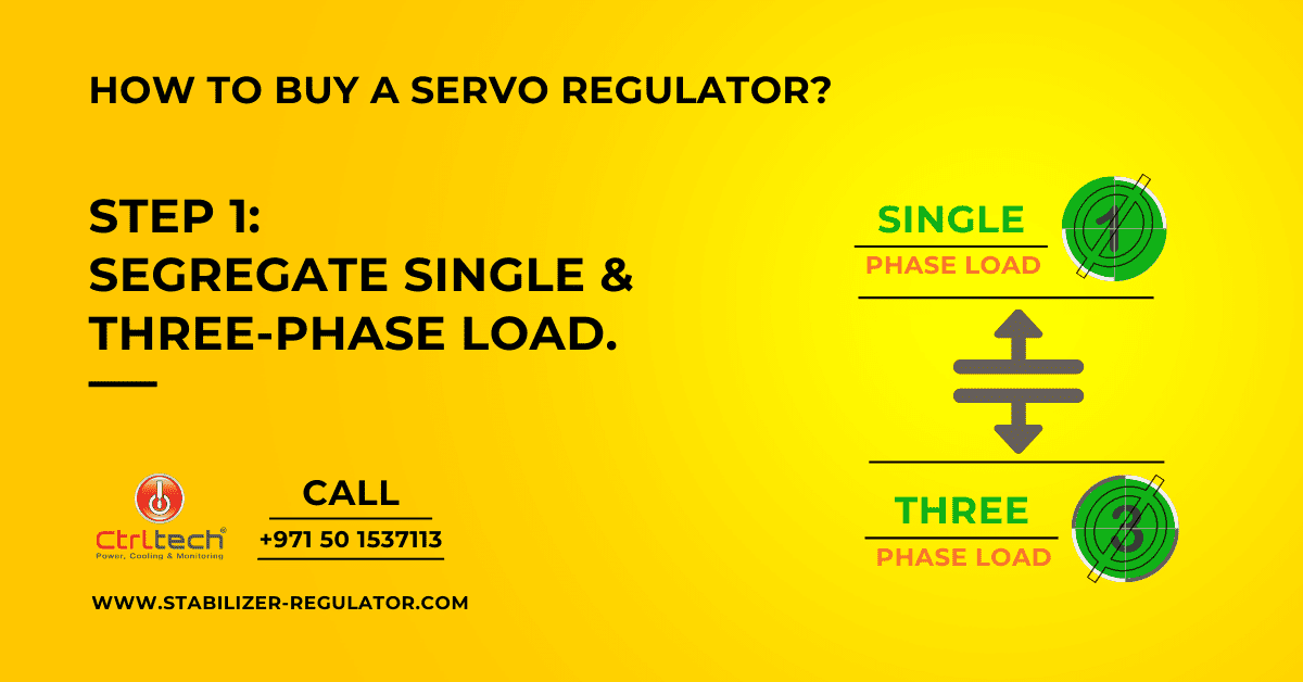
List down the single and three-phase load on a sheet. You will come to know which types of load have a majority. If you have only a single-phase load and the total capacity is less than 20kVA, go for a servo regulator with a single-phase output. If you have a mixed load or only a three-phase load or all single-phase load but a total capacity of more than 20kVA, you must select a three-phase stabilizer.
Step 2: Calculate the total capacity of the servo regulator.
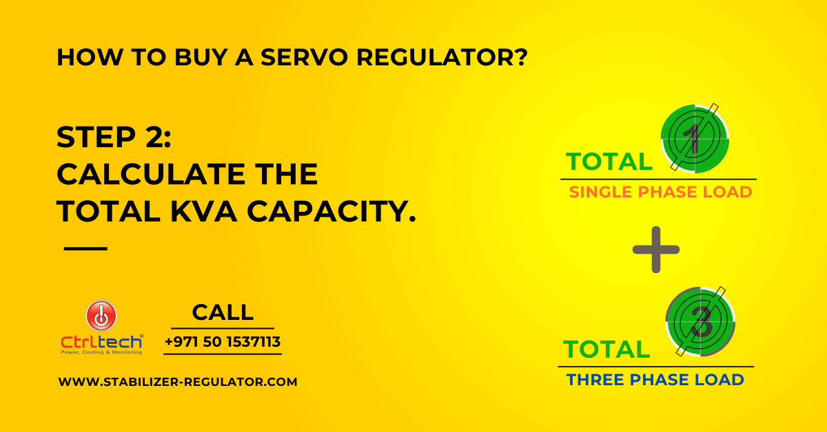
In this step, we need to calculate the total KVA of the load. Since you have already made a list of machines, it is very easy to size. For each mono phase load, you can calculate kVA by multiplying its voltage and current and dividing it by thousand. For 3-phase, multiply the product of line voltage and line current by three and divide it by a thousand. Then some up the kVA capacity of all load to get total capacity. However, we need to consider 20% extra capacity considering future expansion.
Step 3: Select input voltage correction range.
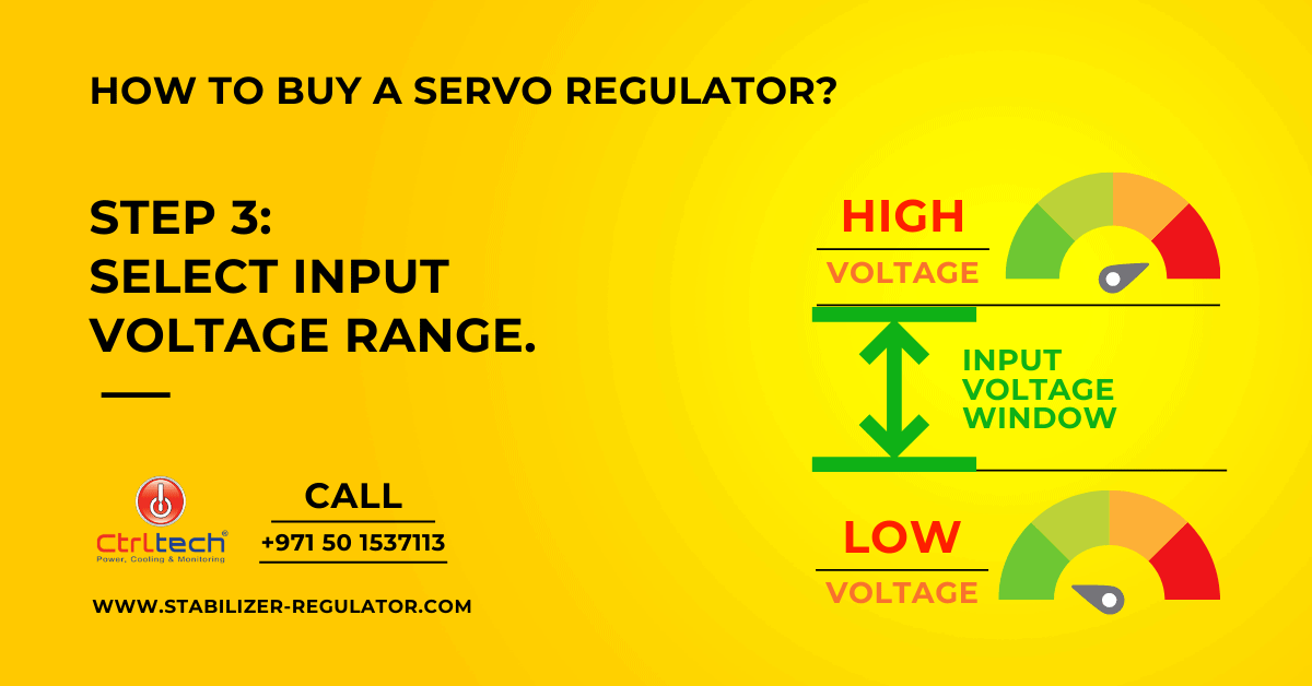
This step is essential. If you select a shorter range, there will be no use in buying a voltage stabilizer. Input voltage correction range or window is nothing but low and high voltage value. And when input is within the two values, a servo regulator will correct it and offer stable output. For example, in servo voltage regulator has an input range of 300 to 480V. Whenever the input voltage is between 300V and 480V, this unit can correct the voltage.
Before buying a system, you should determine this range. You can find out the lowest and highest voltage fluctuation at your facility by recording data with the help of digital meters like Fluke 43. You also can get this data from your local electricity supply company. Suppose data shows that voltage touched to lower value of 280V and shoot to value of 470V then, you should go by unit with input voltage window of 280V to 470V or broader.
Step 4: Select the correct type of stabilizer.
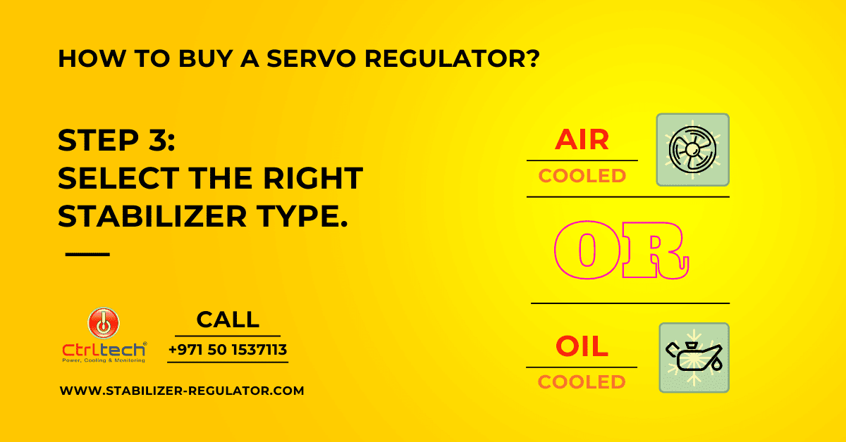
In this step, we need to choose between static or servo and oil-cooled or air-cooled. In short, for industrial loads like machines, lift, elevators, pump rooms, always choose servo voltage regulator. Similarly, for electronic base loads like CNC machines, PLC controllers, Datacenters, select static stabilizers. An oil-cooled unit is more practical than an air-cooled type if you need a mega kVA unit for better performance.
Select the right supplier and servo voltage regulator price.
Once you are ready with capacity and type, it will get a better deal in terms of supplier and price. Shortlist a few suppliers first based on their experience in your market and their service setup. After that, negotiate with them to get a better voltage stabilizer price, warranty terms, and payment terms.
Supply:
- Pen
- Paper
- Internet
Tools:
- Multi meter
- Calculator
- Computer
Where to buy a servo voltage regulator in UAE, Oman, Qatar?
Once you have done your homework on servo stabilizer, you can approach to local CtrlTech dealer or call +971 6 5489626 or send an email at sales@ctrltechnologies.com.
CtrlTech offers door delivery and installation. CtrlTech supplies a wide range of stabilizers in the UAE and Middle Eastern countries. For the supply installation of a significant capacity servo motor regulator in the the UAE, they have a fully skilled team.
Why CtrlTech is a reliable servo voltage regulator supplier in Dubai, UAE?
- CtrlTech offers a voltage stabilizer that complies with all mandatory standards for the manufacturer of the voltage regulator.
- CtrlTech does site study to offer the most suitable type with proper input voltage window. They check the variety of loads, voltage fluctuation range at your facility.
- All servo speed regulators have overvoltage, overcurrent, & short circuit protection as standard or optional features.